ON Semiconductor Advances Li-ion Charging Designs with Small Form Factor Solutions
Like the smartphone evolution of the last decade, other growing markets demand shrinking form factors coupled with added features and portability. The segmenting drone market is exhibiting growth in mini and micro drones. We are seeing significant growth in the hearable, or earbud market, equipped with voice recognition, proximity sensors, noise cancellation and high fidelity. Small Bluetooth speakers fit in the palm of your hand. Wearables in the form of watches, used for both fitness and medical purposes, are growing segments augmenting input to big data analytics of the IoT. Li-ion is the dominant choice for these small form factor markets due to its higher specific energy (Wh/kg), lower cost and flexible form factors, all of which are driving the demand for smaller Li-ion chargers. ON Semiconductor has industry-leading technology for Li-ion chargers in extremely small footprints to enable the migration to smaller charging form factors.
Li-ion CC/CV Charge Profile:
Li-ion typically implements the constant current (CC)/constant voltage (CV) charge profile illustrated in Figure 1 below. Moving from left to right, an empty cell begins charging with a gentle charge (~C/5), or the “pre-charge.” Li-ion prematurely ages if too much current is applied when near empty. Once the cell voltage rises to VBATMIN (typically 3.6V for cobalt), then it is safe to enter CC mode, with the maximum allowable charge current specified in the cell data sheet (~1C). This maximizes the Time to Charge (TTC). When the cell voltages reaches VFLOAT, or the maximum voltage, again specified in the cell datasheet, the charger then enters CV mode. CV mode clamps the voltage and the current entering the cell naturally tapers as the cell approaches full charge. Finally, as the tapering charge, current approaches C/10 to C/20 the charger terminates the charge.
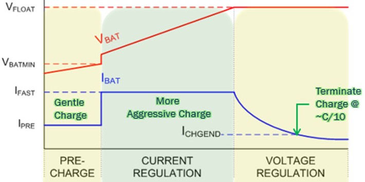
Figure1
The values for VFLOAT, VBATMIN, IPRE and IFAST, can be found in the battery datasheet. Many Li-ion chargers require a companion processor to program its internal registers across I2C in order to produce the CC/CV charge profile of Figure 1. ON Semiconductor’s FAN54120 stand-alone Li-ion charger autonomously executes the CC/CV Charge profile depicted in Figure 1, without any I2C registers, or firmware. This eliminates the need for a companion processor, thus reducing cost, space and complexity. It simply works out of the box, reducing time to market. Because there is no firmware, the FAN54120 is tamperproof, another advantage for security-sensitive applications like medical or IoT.
The FAN54120 standalone charger is an extremely low form factor. Now shipping in a 2mm x 2mm DFN package, and a soon to be released, 1.36mm x 0.76mm WLCSP package.
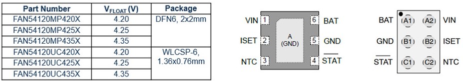
Figure 2
FAN54120 500mA Linear Stand Alone Charger:
The FAN54120 references an external rset resistor (Figure 3) to autonomously produce the CC/CV charge profile of Figure 1, across a wide range of battery capacities (Figure 3, blue column). For example (Figure 3), if the cell can handle 500mA maximum charge, by choosing a 1kΩ rset (IFAST=500mA), the FAN54120 will automatically pre-charge at 100mA (IFAST/5), a transition to 500mA (IFAST) for CC mode, and then terminate the charge @ 50mA (IFAST/10), for a 750mAh battery.
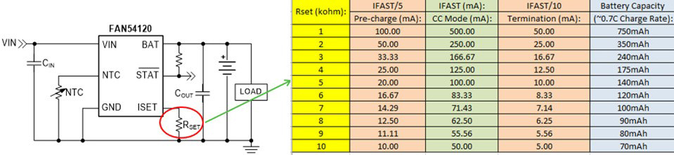
Figure 3
For smaller Li-ion battery capacities like 140mAh (Figure 3), a 5KΩ rset resister results in a 20mA pre-charge, 100mA CC Mode charge current, followed by a 10mA charge termination.
The FAN54120 supports JEITA “Safe-to-Charge” temperature operation with an external NTC. The FAN54120 tolerates a maximum 28V input voltage, while operating up to 6V input, and exhibits a world-class quiescent current of only 150nA. This ensures the FAN54120 will not over-discharge the cell in between charges. Finally, the FAN54120 offers 0.5% CV accuracy preventing inadvertent OVP (Over Voltage Protection) tripping of less expensive cell protection circuits with + 50mV tolerance.
Markets and applications include earbuds, wearables, Bluetooth speakers and headsets, IoT devices, mini and micro drones, cameras, E-cigarettes, toys and games.
Earbud Cradle Charger Application Block Diagram:
The typical battery capacity for an earbud cradle charger ranges from 270mAh to 550mAh, which is right in the sweet spot for the FAN54120.
The block diagram Figure 4 shows the FAN54120 receiving 5V VBUS directly from USB (does not have to be USB Type C), where 5kΩ pull-down resistors on CC1 and CC2 informs a connected source this is a valid sink. The LC709204 performs fuel gauging and is configured by the RSL10 BLE. The RSL10 communicates with a phone app and wakes up every second to learn if an earbud is attached (BLE: RSI), then enables the FAN4860 5V boost. Boost current consumption is reduced when earbuds are not attached.
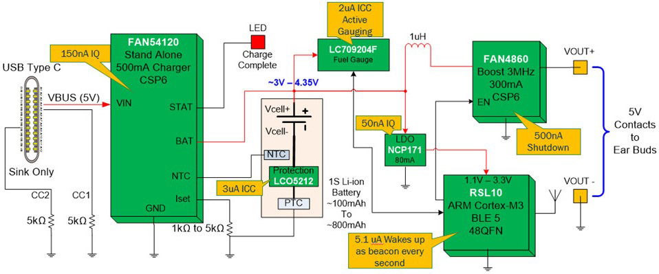
Figure 4
The recharge interval for the above cradle charger, assuming a fully charged 500mAh battery, will be >5 years, due to the ON Semiconductor’s low power product performance.
Learn more about FAN54120 stand-alone Li-ion charger and the LC709204 Battery Fuel Gauge for 1-Cell Lithium-Ion/Polymer to be used for your design needs!